PLC ENGINEERING

plc

Home

plc

  • Studio 5000 and RSLogix 5000 Firmware and Version Management: A Rigorous Guide
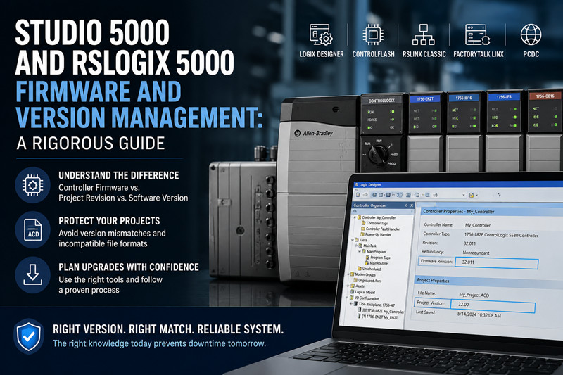
    Studio 5000 and RSLogix 5000 Firmware and Version Management: A Rigorous Guide Sep 02, 2026
      Firmware is the operating system that runs on the controller. Project revision is the format version of the .ACD file. These two numbers are frequently confused, and the confusion is expensive. A maintenance engineer who mistakes one for the other can convert a healthy project into a file that no installed software can open, or send a running production line through an unplanned firmware download for which no backup exists. Correct terminology follows Rockwell Automation usage: Logix Designer, ControlFLASH, RSLinx Classic, FactoryTalk Linx, and the Product Compatibility and Download Center (PCDC).   1. Definitions   1.1 Controller firmware   Firmware is the executable operating system stored in nonvolatile memory on the controller. For a ControlLogix or CompactLogix controller, the firmware implements the Logix execution engine: it runs the task model, executes the routines, communicates over the backplane and the network, and provides the services that Logix Designer calls during an online session. A controller without firmware is inert. New controllers ship from the factory with firmware already loaded, and the same physical hardware can run different firmware revisions over its service life. Rockwell identifies firmware by a revision number. The revision is the number shown in RSLinx Classic or FactoryTalk Linx when the engineer browses to the controller, and it is the number that must be weighed against the software version on the PC. When this guide says "controller revision," it means that firmware revision number.   1.2 Project revision   A Logix Designer project is a single file with the .ACD extension. The file has its own format version, and that format version is the project revision. When a dialog says "project revision 32," it is describing the file format, not the controller. The project revision is written into the file by the software that created or last saved it. The project revision and the controller revision usually match in a healthy system, because Logix Designer creates a project at the revision of the controller it targets. The match is a convention, not an identity. A project at revision 32 can target a controller at firmware 32, and the two numbers happen to be equal. The confusion begins when an engineer treats the project revision as if it were the controller firmware, or the controller firmware as if it were a file property.   1.3 Software version   The software version is the version of the installed application: RSLogix 5000 for versions 1 through 20, and Studio 5000 Logix Designer for version 21 and later. Rockwell renamed RSLogix 5000 to Studio 5000 Logix Designer starting around version 21, released in 2012. The change was a rebranding and a packaging change, not a new product. The application that opens .ACD files is the same lineage, and the version numbering continued without a break. Version 20 is therefore RSLogix 5000, and version 21 is Studio 5000 Logix Designer. The name matters only near that transition point. An engineer should read "Studio 5000 version 32" and "RSLogix 5000 version 20" as the same kind of quantity. Each software version has a native project revision. Studio 5000 Logix Designer version 32 creates and edits projects at revision 32. The software can open projects at older revisions under conditions described below, and it can create projects for controllers at older firmware revisions under conditions as well. The native pairing is the relationship that matters: software version N pairs with project revision N and controller revision N.   1.4 Module firmware   The controller is not the only device with firmware. Every intelligent module in a Logix system carries its own: the 1756-EN2T Ethernet communication module, the 1756-IB16 and other discrete I/O modules, the 1756-IF8 and other analog modules, the 1756-CNB and 1756-DNB bridges, and the 5069 and 1769 I/O families. Each module has its own firmware revision, and each is updated separately with ControlFLASH. Module firmware matters for two reasons. The project stores the expected firmware revision for every module in the I/O configuration, and Logix Designer compares expectations against reality at online time. Communication modules also sit on the online path to the controller, so a module with incompatible firmware can block the connection before the engineer ever reaches the controller. Module firmware and controller firmware are updated with the same tool, but they are different operations, and an upgrade plan must treat them separately.   2. The compatibility model   The compatibility model has three inputs: the software version, the project revision, and the controller revision. The rules below describe how the three may combine. Once the rules are stated, every dialog and every failure mode becomes readable.   2.1 Project files: no forward compatibility, limited backward compatibility   A project saved by a newer version of the software cannot be opened by an older version. This rule has no exceptions in the Logix product line. If a project was created and saved in Studio 5000 Logix Designer version 33, no installation of version 32 can open it. The older software does not understand the newer file format, and Rockwell does not ship a downgrade converter for project files. Backward compatibility exists and is limited. An older project opens in newer software, and the newer software converts it. The conversion is one-way. After the newer version saves the file, the project revision has advanced, and the older software can no longer open it. A project at revision 20 that is opened in version 33 and saved becomes a revision 33 project. The original revision 20 file is gone unless a copy was kept. This is the first expensive failure mode. An engineer opens an old project to look at a routine, the software prompts to convert, the engineer accepts, saves, and the plant loses the ability to open that project with the old software that still matches the running controllers. The safe practice follows directly from the rule: keep the original file untouched, and convert into a new file name.   2.2 Software version and controller revision: the online requirement   Going online is the operation where software and controller meet directly. Logix Designer establishes a communication path through RSLinx Classic or FactoryTalk Linx, finds the controller, and compares versions. The comparison is strict. To go online with a controller, the software version must be compatible with the controller's firmware revision. The practical expression of the requirement: software at a version equal to or newer than the controller revision can go online. Software older than the controller revision cannot. A controller at revision 32 requires software at version 32 or newer. Version 31 cannot go online with that controller, and no driver setting or compatibility mode changes that fact.   2.3 Upload and download   Upload is the transfer of the project from the controller to the PC. Upload works when the software version is equal to or newer than the controller firmware revision. The software reads the program from the controller, reconstructs a project, and writes the file at the revision of the controller it read. Uploading from a controller at revision 24 with version 32 software therefore produces a project at revision 24, and that file is openable by software at version 24 or newer, including the older software the plant already owns. Uploading with software older than the controller revision is not possible: the older software cannot interpret the data structures of the newer controller. A controller at revision 32 with only version 30 software available cannot be uploaded. The fix is to obtain version 32 software or newer, not to attempt workarounds. Download is the transfer of the project from the PC to the controller. Download requires the project revision to match the controller revision, unless the engineer explicitly changes the controller revision as part of the download. When the revisions differ, Logix Designer offers to change the controller revision before it downloads the project. Changing the controller revision means flashing new firmware into the controller. There is a legitimate way to make the two sides match without a conversion: the New Project dialog in Logix Designer offers a revision list for the selected controller, and that list includes revisions older than the software version. A plant with version 32 software can create a project at revision 24 for a v24 controller, and the file is written at revision 24. This is how an OEM produces a deliverable that an older software version can open, and it is the correct tool when the project revision and the controller revision must be aligned by design. The download path is where the second expensive failure mode lives. The change-controller-revision prompt appears during a routine download, an engineer accepts it without reading it, and the controller receives new firmware. A running machine whose controller was never backed up loses its program if the flash fails partway. Even a successful firmware change can leave I/O connections and module firmware expectations in an inconsistent state, because the new controller revision may expect newer module firmware than the chassis actually runs.   2.4 What the revision mismatch dialogs actually mean   Three dialogs dominate the field reports. The first is the project open error. The software reports that the project was created with a newer version of the software and refuses to open the file. No workaround exists inside the older software. The fix is to obtain the newer software version, or to ask the source of the file for a copy at the plant's revision, which the newer software can produce for projects it can open. The second is the Go Online mismatch. The software finds the controller, sees a revision difference, and offers to change the controller revision. Accepting the offer flashes the controller. The dialog is a request for permission to change firmware, not a notice. The safe response is Cancel, followed by a decision about which side should move: install matching software, or plan a controlled firmware upgrade. The third is the download mismatch with the change-controller-revision option. It is the same operation as the second, reached through a different path. The meaning is identical: the project revision and the controller revision differ, and the software proposes to make them equal by writing new firmware to the controller. The Who-is-online list in Logix Designer shows the engineers currently connected to each controller and the controllers each connection targets. It belongs in this discussion because the Go Online sequence is where an engineer first sees the revision of the target controller, and where an unplanned acceptance of the change-controller-revision offer does its damage. The dialog appears once per online attempt, it is phrased as a routine question, and the cost of accepting it without preparation is an altered or bricked machine. The Go Online flow is also where the engineer sees whether the controller can be reached at all: if the communication path fails before the version comparison, the problem is the driver or the network, and if the comparison fails, the problem is the revision.   2.5 Why the three numbers line up   The alignment of software version, project revision, and controller revision is not accidental. When an engineer creates a new project, Logix Designer asks for the controller catalog number and for the controller revision. The project file is written at the selected revision, and that revision is stored as the target. A healthy machine runs a controller at the revision the project targets, and the project lives at the revision of the software that manages it. Drift in any one of the three numbers produces one of the dialogs above. Online edits add a second kind of drift. An engineer who goes online and edits logic changes the program stored in the controller without changing the .ACD file on the PC. The controller and the file now differ, even though every version number matches. This is why a full upload belongs in any upgrade procedure: the upload captures the actual state of the controller, including edits that were never saved to the file.   2.6 Common situations, read through the model   Four situations recur in support requests, and each one is the compatibility model in action. Situation one: an OEM sends a project file at revision 33, and the plant runs Studio 5000 version 30. The file will not open. The plant either installs version 33, or asks the OEM for a project at revision 30, which the OEM's newer software can create. Neither option changes the controllers, so the plant's existing online capability is unaffected. Situation two: a replacement controller arrives from the warehouse and the plant cannot go online with it. The replacement was flashed to a newer firmware revision than the plant's software supports. The options are to flash the replacement down to a revision the plant's software supports, if that revision exists for the catalog number, or to upgrade the plant's software. Flashing down is a firmware operation with the same risks as any other flash, and it needs the same backup discipline. Situation three: an engineer downloads a project and the software asks to change the controller revision. The engineer accepts, and after the download the I/O tree shows module faults. The controller revision moved, the module firmware did not, and the project's module expectations no longer match the chassis. The fix is a planned module firmware upgrade, which is why the procedure in section 6 treats the whole chassis, not only the controller. Situation four: an engineer cannot upload from a controller that a contractor upgraded during commissioning. The contractor flashed the controller to revision 32 and the plant owns version 30 software. Upload is impossible until the plant obtains version 32 or newer. This situation is common after third-party work, and it is why the controller revision belongs on any handover checklist.   3. Hardware firmware limits   Each controller family has a range of firmware revisions it can run. The figures below are the well-established limits. Rockwell adjusts support policy over time, and the authoritative source for any specific catalog number is the Product Compatibility and Download Center (PCDC). Check the PCDC before planning an upgrade. A firmware revision that does not exist for a given catalog number cannot be selected in ControlFLASH in any case. Controller family | Catalog numbers | Maximum firmware (typical) | Notes ControlLogix 5560 | 1756-L61, 1756-L62, 1756-L63 | approximately v20 | Rockwell ended feature development for the L6x family at that point. The exact supported range depends on the catalog number; check the PCDC. ControlLogix 5570 | 1756-L71 through 1756-L75 | approximately v24 | The L7x family tops out near v24. Check the PCDC for the exact range. ControlLogix 5580 | 1756-L81 through 1756-L85 | v24 and newer | The L8x family requires v24 or newer and will not accept older firmware. ControlLogix 5580, E series | 1756-L81E through 1756-L85E | v28 and newer (general) | The 5580 family generally requires v28 or newer. Check the PCDC for the current maximum. CompactLogix 5370 | 5069-L306ER and related 5069 catalog numbers | v30 and newer (general) | The 5069 family generally requires v30 or newer. Check the PCDC for the current maximum. CompactLogix 5370 | 1769-L16ER through 1769-L37ERM | approximately v20 to v36 | The supported range depends on the model and on Rockwell support policy. Check the PCDC for the exact figure for your catalog number. Three practical consequences follow from the table. First, an L61 at revision 20 cannot be upgraded to revision 24; the hardware does not support it, and no firmware file at revision 24 exists for that catalog number. Second, an L81 cannot run revision 20 firmware; the controller requires revision 24 or newer and will not accept older firmware. Third, the maximum firmware for the 5580 and 5069 families is a moving target: Rockwell publishes new revisions over time, and the current maximum is exactly the kind of figure the PCDC exists to state. When a plant plans a migration from an L6x to an L8x, the firmware jump from approximately v20 to v24 or newer is part of the project scope, along with the software jump from RSLogix 5000 to a newer Studio 5000 version. The same reasoning applies to a migration from a 1769 CompactLogix to a 5069 CompactLogix: the new controller family sets a new firmware floor and a new software floor, and the old project must be converted into a new project at the new revision before it can be downloaded. Hardware that has reached the end of its firmware range is often the same hardware that has become hard to source, which is why Allen-Bradley spare parts for legacy ControlLogix and CompactLogix platforms remain a normal procurement item for plants that cannot migrate yet.   4. Multiple software versions on one PC   Multiple versions of RSLogix 5000 and Studio 5000 Logix Designer can be installed on the same PC. Rockwell designed the installers to coexist, and many engineers do run version 20 and version 32 on one machine. The coexistence is workable, and it is messy. Licensing is the first complication. RSLogix 5000 and Studio 5000 use FactoryTalk Activation, and each software version needs its own activation. An activation that covers version 32 does not automatically cover version 20. A plant that keeps both installed must keep both activations valid, and an expired activation for one version surfaces as an error that looks like a software fault. Windows compatibility is the second complication. The oldest RSLogix 5000 versions predate modern Windows and do not run on Windows 10 or Windows 11. Version 20, for example, was released in the Windows XP and Windows 7 era, and running it on a modern operating system typically requires a virtual machine. The compatibility matrix in the PCDC states the supported operating systems for each software version. The honest summary: the older the software, the older the Windows it needs. Coexistence itself is the third complication. Different versions share services such as RSLinx Classic and FactoryTalk Linx, and version conflicts surface as drivers that disappear, activation errors, and projects that open in the wrong application when file associations point at the last installed version. A version that worked alone can start failing after a second version is installed. The common engineering solution is a dedicated laptop or a virtual machine per version. A plant with controllers at v20 and at v32 keeps one machine with RSLogix 5000 v20 and one with Studio 5000 v32, and does not mix them. The pattern costs hardware and desk space, and it buys certainty. A plant that keeps a v20 machine alive is usually the same plant that keeps PLC spare parts on hand for hardware Rockwell no longer sells. The virtual machine approach has an extra advantage: the VM image itself is a backup, and a corrupted installation is restored by copying the image rather than by reinstalling the software and re-entering activations.   5. Module firmware versus controller firmware   A Logix chassis contains the controller and its modules, and each module runs its own firmware. The project stores the expected firmware revision for every module in the I/O configuration. When Logix Designer goes online, it compares the expected module revisions against the actual revisions in the chassis and reports differences. Module firmware is updated with ControlFLASH, the same tool used for the controller. The operation is per module: select the module in the flash tool, select the target revision, and flash. The 1756-EN2T Ethernet module is the module most often flashed, because its firmware controls the network path and because Rockwell publishes new EN2T revisions to correct communication defects. The practical rule: module firmware upgrades belong in the same maintenance window as controller firmware upgrades, and they are verified with the same discipline. A project that expects EN2T revision 5 on a module that runs revision 3 produces a mismatch at online time, and the mismatch either blocks the connection or degrades it, depending on the module and the size of the difference. Keep module firmware consistent with the project's expectations, and change both sides deliberately, never one side by accident. A controller firmware upgrade that raises the controller beyond the firmware of its communication modules is a common source of module fault and connection failed reports after an otherwise clean upgrade.   6. The safe firmware upgrade procedure   The procedure below is ordered. Every step exists because a skipped step has caused a real failure. Follow the steps in sequence, and do not merge steps. 1. Verify the current state. Open RSLinx Classic or FactoryTalk Linx, browse to the controller, and record the current firmware revision. Record the revision of every module in the chassis as well, from the I/O configuration in the project or from module properties. The record is the baseline for the entire operation, and it is the reference for the post-upgrade verification. 2. Back up the project. Close the project, copy the .ACD file to two separate locations, and record the project revision. Do not convert the project as part of the backup. The backup must be a byte-for-byte copy of the file that matches the running system. 3. Perform a full upload. Go online with the current software, upload the project from the controller, and save the uploaded copy under a separate name. The upload is the second backup, and it is the one that matters if the .ACD file and the controller have drifted apart. Controllers can contain logic that the file does not, because engineers make online edits. The upload captures the actual state. 4. Check the compatibility matrix in the PCDC. Verify three things: the target firmware revision exists for the controller catalog number, the software version planned for the post-upgrade connection supports that firmware revision, and that software version runs on the operating system of the PC that will go online. A failure in any of the three cancels the upgrade until it is resolved. This step also identifies the module firmware revisions that the target controller revision expects, so the module list from step 1 can be checked against it. 5. Confirm the maintenance window. A firmware download interrupts the controller. The controller stops executing the program for the duration of the flash, and I/O connections drop. Confirm that the process can tolerate the interruption, that the operators have been informed, and that the machine is in a safe state. Do not upgrade a running machine outside a maintenance window, and do not upgrade a machine in the middle of a batch. 6. Run ControlFLASH. Launch ControlFLASH, select the controller, select the target revision, and start the flash. Do not interrupt the flash once it starts. A power loss or a communication break during the flash can leave the controller with a corrupt firmware image. The controller may recover through a boot mode, and the recovery is not guaranteed. Wait for the completion message before touching anything. 7. Verify the result. Power-cycle or reset the controller as the flash tool directs. Go online with the planned software version and confirm that the revision shown in Logix Designer matches the target. Check the I/O connections: every module in the I/O tree should show its expected state, and module firmware mismatches surface at this point. Confirm that the program runs: place the controller in Run mode and observe execution, task timestamps, and I/O values. Keep the pre-upgrade backups until the machine has completed a full production cycle on the new firmware. Module firmware upgrades follow the same procedure, with step 6 repeated for each module. The verification in step 7 then checks the module revisions in the I/O tree instead of the controller revision.   7. Firmware upgrade checklist   Condensed checklist for the maintenance planner: · [ ] Baseline recorded: controller revision and module revisions documented · [ ] Project backed up at its current revision, two copies, not converted · [ ] Full upload performed and saved under a separate name · [ ] PCDC checked: target firmware exists for the controller catalog number · [ ] PCDC checked: planned software version supports the target firmware · [ ] PCDC checked: software version supports the PC operating system · [ ] Module firmware expectations checked against the target controller revision · [ ] Maintenance window confirmed with operations · [ ] Machine in a safe state, no active batch · [ ] ControlFLASH run to completion without interruption · [ ] Controller reset or power cycle performed as directed · [ ] Online verified: controller revision matches the target · [ ] I/O connections verified module by module · [ ] Program confirmed running in Run mode · [ ] Pre-upgrade backups retained until one full production cycle completes   8. FAQ   Q1. Can version 30 open a project saved in Studio 5000 version 32? No. A project saved by a newer version cannot be opened by an older version. Version 30 cannot read the revision 32 file format. Obtain version 32 or newer, or ask the source of the file for a copy at revision 30. Q2. What does the controller revision mismatch message mean when I go online? It means the software version and the controller firmware revision are not compatible, and the software offers to change the controller revision, which writes new firmware to the controller. Cancel the offer unless the change is planned, backed up, and scheduled. Q3. Can I upload from a controller whose firmware is newer than my software? No. Upload requires software at a version equal to or newer than the controller revision. Install matching or newer software before the upload. Q4. Is a firmware upgrade reversible? A controller can be flashed back to an older revision if that revision exists for the catalog number. The reversal is itself a firmware operation with the same risks. A converted project is not reversible: once the newer software saves a converted file, no older software can open it. Q5. Can I run version 20 and version 33 on the same PC? In principle, yes. The practical limits are licensing, Windows compatibility, and shared-service conflicts. Version 20 does not run on modern Windows without a virtual machine. Most plants use a dedicated laptop or VM per version. Q6. What is the difference between controller firmware and module firmware? Controller firmware is the operating system of the controller. Module firmware is the operating system of each individual module, such as a 1756-EN2T. Both are updated with ControlFLASH, and both must match what the project expects. Q7. Where do I find the exact maximum firmware for my controller? In the Product Compatibility and Download Center (PCDC) at Rockwell Automation. The PCDC states the available firmware revisions for each catalog number and the compatible software versions. Consult it before every upgrade.   9. The rule that governs every case   The compatibility model reduces to one sentence: the software version, the project revision, and the controller revision must form a consistent set, and every change to one member of the set is a planned operation. A project file that will not open, an online session that will not start, and a download that wants to change controller firmware are all the same underlying condition: the set is inconsistent. The engineer's job is to identify which member is out of line, decide which member should move, and move it with a backup and a maintenance window in place. For plants that run legacy hardware, the set has a fourth member: the hardware itself. A controller whose firmware range has ended is a controller whose spares are scarce, and the planning horizon for a migration starts at the moment the firmware limit is reached. Allen-Bradley spare parts and ControlLogix spare parts keep legacy lines running while the migration is planned, and the version discipline in this guide keeps the software side of the set stable for as long as the hardware runs. The discipline costs little. The alternative costs a production line. URL Slug: studio-5000-firmware-version-management-guide ------------------------------------------------------------------------------------------- 🏢 About TZ Tech   TZ Tech is a leading supplier of industrial automation, electrical, instrumentation, and telecommunications components. We specialize in sourcing ready-to-ship distributor stock, allowing us to offer highly competitive pricing and short lead times. Thanks to our extensive inventory, we can even source rare and discontinued parts that are hard to find elsewhere.   🛡️ Our Quality Commitment   We understand that quality is your top priority. Every component undergoes a strict screening and inspection process so you can buy with absolute confidence. For legacy or discontinued parts, we believe in complete transparency and will always provide an honest, accurate report on the product's condition. Plus, all brand-new parts come backed by a full 1-year warranty.   ✉️ Get in Touch     Have a project or a part you need? Send us your inquiry today! Our team is dedicated to providing a fast response within 6 hours (excluding weekends).

  • ControlNet Troubleshooting: A Field Procedure That Gets the Net Back
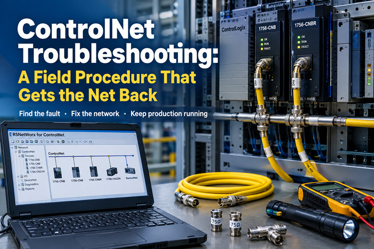
    ControlNet Troubleshooting: A Field Procedure That Gets the Net Back Sep 09, 2026
      At 2:17 in the morning the phone wakes you, and the voice on the other end skips the hello. Node 14 dropped and the line is down. Scheduled traffic through the 1756-CNB stopped forty minutes ago, the drives are faulted, and the shift electrician has already reseated every connector he can reach. He wants to know if you are coming. You are coming. Before you get in the truck, take this article with you. Here is the situation you will walk into. A ControlNet trunk built from 1786-RG6 coax, tapped into a row of 1756-CNB and 1756-CNBR modules in ControlLogix racks, a 1788-CN2DN or two carrying I/O down to DeviceNet, and a schedule that RSNetWorx for ControlNet wrote years ago and nobody has backed up since. Rockwell lists ControlNet as Active-Mature, which is a polite way of saying it still supports the product but is not building more of it. The company would rather sell you EtherNet/IP on 1783 switches, and it is right to try. But your plant still runs on coax, and it has to run tomorrow. This is the field procedure that gets the net back. Do the steps in order and do not skip the boring ones, because the boring ones are where these calls usually die.   Tools you need before you start   Round these up before you leave the shop. Every trip back to the truck for a missing part costs twenty minutes of a night that is already long. · RSNetWorx for ControlNet, installed and proven on your laptop. Know which version you carry, and know that the EDS files on that laptop match the devices on the net. A laptop that has not seen the plant in two years will waste your first hour updating itself. · A ControlNet interface for the laptop. The 1784-PCC CardBus card and the 1784-U2CN USB adapter are the two you will meet in the field. Load the driver and configure it in RSLinx before you leave, and test the card against a live net at the shop. Testing it for the first time in a dark panel at 3 AM is a bad plan. · The backup schedule file. This is the .cnc file that RSNetWorx saves when you commission a network. If you do not have one, your night just got longer. If you have one but it is five years old, treat it with suspicion until you have compared it to the running network. · Physical spares: a short length of 1786-RG6 coax, two 75-ohm terminators, one spare tap, and a handful of BNC connectors. Take a full drum of cable if the trunk is long or runs outdoors. · A known-good 1756-CNB or 1756-CNBR, flashed to the firmware your plant runs, in case step 6 becomes necessary. · A multimeter, a flashlight, a small mirror for reading node addresses behind panels, and the EDS files for every third-party device on the net, carried on a USB stick.   Run the ladder in this order   ControlNet faults fall into four bins: the cable, the module, the schedule, and the node. The failure modes look alike from the operator screen, and that is the trap. A node that dropped because a terminator is missing looks identical to a node that dropped because its address collides with another node. The order of attack is not a preference. Check the physical layer first, then the module, then the schedule, then the node, and swap hardware last. Each step eliminates a whole class of faults, and none of them requires you to trust the story the operator told you at 2 AM.   Step 1: Check the physical layer first   ControlNet is a scheduled, time-sliced network running 5 Mbit/s on 75-ohm coax. Every node gets a guaranteed slot in a repeating frame, and the whole scheme depends on the signal arriving clean at every tap. Reflections kill that signal, and reflections come from bad geometry: open ends, wrong cable, stubs, water. Most "the net went down at 2 AM" calls end here, in the cable, not in the schedule. Start at one end of the trunk and work your way to the other. Power down what you can before you touch coax. Do not hot-unplug a live trunk while the plant is depending on it, and never pull a connector to "see if it sparks." It will not spark, and you will have just dropped the net. Check the terminators first. A ControlNet trunk needs exactly two, one at each physical end, and both must be 75 ohm. The 1786-XT is the correct part for this system. A missing terminator leaves the end of the cable open. The signal reflects off that open end, and nodes near it go marginal and drop when the cabinet warms up or a large motor starts. An extra terminator is just as bad when it hangs off a tap in the middle of the trunk, because it turns a healthy segment into two stubs. The rule is short: two terminators, at the ends, nothing else on the cable. Check every BNC connector on the trunk. Seated means you feel it click into place and you cannot rotate the shell against the jack. A connector that spins is a crimp that failed years ago and has been getting worse since. Look at the center pin. It should be clean, straight, and fully engaged. Water in a connector reads as intermittent loss that no schedule change will ever fix, and corrosion on the shield braid does the same. When you find a bad connector, cut it off and re-terminate with a fresh one rather than tightening it and hoping. Check the cable itself. The trunk must be 1786-RG6 quad-shield coax. RG-59 will carry the signal a short way and then lie to you, and the leftover TV coax someone used to patch a broken section is worse than no patch at all, because it passes the DC checks and fails under load. If someone spliced the trunk with a barrel connector, that splice is a reflection point and a future 2 AM call. If someone daisy-chained from one module's BNC straight to the next module's BNC instead of using taps, you are looking at a stub that should never have been built. Devices attach through taps, with a short drop cable from the tap to the node. Keep every drop to a meter or less and route it clear of power cables. Then run the numbers. A single ControlNet segment is limited to 1000 m of RG-6 and 48 nodes. If your plant exceeds either limit, a repeater must sit in the path, and the problem node is probably on the far side of that repeater. Look for the repeater and check its power before you go any deeper. While you are walking the cable, look for the obvious damage: coax crushed behind a swing panel, cable routed through a drain, water standing in a below-grade pull box, a fork truck scar on the jacket. ControlNet cable failures are rarely mysterious once you look at the actual cable. If the whole net will not come up, you are hunting a short or an open. Every node's network LED dark or flashing at the same time means the trunk is the problem. It is not forty modules that all failed in the same hour. Isolate the fault methodically. Power down nodes one at a time, pull their drops at the tap, and watch whether the rest of the net comes solid green. When you pull the drop that fixes the net, you have found the guilty piece. It is usually a crushed cable, a wet connector, or a tap that took a hit from a ladder. Fix that one thing and the net comes back whole.   Step 2: Read the module LEDs   The 1756-CNB and 1756-CNBR tell you a lot from the front panel if you read the indicators in pairs. The 1756-CNB carries two indicators, one for module status and one for network status. The 1756-CNBR carries three: module status plus one per redundant channel. The module LED tells you whether the hardware is alive. The network LED tells you whether it is talking. Read the module LED first. A module that is dead on the backplane will never talk on the net, no matter how good the cable behind it is. Indicator | Pattern | What it means | What to do Module LED | Off | No power, or the module is not seated on the backplane | Reseat the module firmly. Check the chassis power supply and the slot. Module LED | Solid green | Normal operation | Nothing. Move to the network LED. Module LED | Flashing green | Self-test in progress, or firmware being updated | Wait. If it still flashes after ten minutes, cycle power to the chassis. Module LED | Flashing red | Recoverable fault, usually configuration or firmware related | Check the firmware revision against the I/O tree in Studio 5000. Cycle power. Module LED | Solid red | Unrecoverable fault | Reseat once. If the red returns, the module is dead. Go to step 6. Network LED | Off | Module is alive but not talking on the trunk | Check the tap, the drop cable, and the trunk behind this node. That is step 1 work. Network LED | Solid green | Online and passing scheduled traffic | Normal. Nothing to do. Network LED | Flashing green | Powered but not communicating with the network | The node cannot hear the net. Check the terminator, the tap, and the node address. Network LED | Red, solid or flashing | Duplicate node address, or a serious network fault | Power the node down. Check its address against every other node. Check the trunk. On a 1756-CNBR running redundant media, the two network indicators should mirror each other. One solid green while the other shows red means the fault lives on that channel's cable or terminator, not in the module. Swap the suspect channel's cable and terminator before you condemn the module, and you will save yourself a part. One field rule carries you a long way. When every node on the net misbehaves at the same time, it is the trunk. When exactly one node misbehaves and the rest sit solid green, it is that node, its tap, its drop, or its address. Make that split early and you will not waste an hour working the wrong end of the ladder.   Step 3: Go online with RSNetWorx and verify the schedule   Get RSNetWorx for ControlNet online against the network before you change anything. Select the driver that matches your interface card, browse, and let the software discover the net. Write down what it finds: how many nodes, which ones are scheduled, which ones are not. That list is your map for the rest of the night. Then settle the question of who owns the schedule. On ControlNet, the schedule is the arrangement of who talks in which time slot. It lives in two places. The .cnc file holds it on whoever commissioned the network, and every scheduled node holds a copy of its own part. When RSNetWorx goes online and its file disagrees with the network, it asks which one to keep. If the network has been running fine and your file is stale, upload from the network and save it under a fresh name. If the network is the mess you were called to fix and your file is the good one, restore from the file. Make that decision once, deliberately, and say it out loud before you click. The wrong choice wipes a working schedule, and nothing in RSNetWorx will warn you twice. Open the network properties and read two numbers: the NUT and S_max. The NUT, or network update time, is the length of the repeating frame that carries all scheduled traffic. The default is 2 ms, and most plants never need more. S_max is the highest node address the schedule will accommodate. It must sit above your highest scheduled node. If someone added a node at address 60 while S_max sat at 50, that node will never be scheduled, no matter how many times you commission. Raise S_max, then commission. This one setting has sent more engineers in circles than any cable fault I have seen. RSNetWorx also shows the split between scheduled and unscheduled bandwidth. Scheduled traffic gets a guaranteed slot in every frame. Unscheduled traffic, the explicit messages, uploads, and programming traffic, fills whatever space is left. When a new connection will not fit the schedule, RSNetWorx tells you plainly. The fix is a larger NUT or fewer scheduled connections, never magic and never a second commission with the same numbers. While you are online, look at each scheduled node. RSNetWorx marks devices that are present but missing from the schedule, and it marks devices it cannot identify. Both conditions show up here first, and both have different fixes. If the net looks healthy in RSNetWorx, the problem is narrower than the phone call suggested, and step 4 will find it.   Step 4: Find the missing node   The plant says node 14 is gone. RSNetWorx says it sees 47 of 48 nodes. Do not trust the node number painted on the panel door. Trust the address the device is actually set to, because the two have disagreed since the day the panel was built. First, confirm the address. A 1788-CN2DN takes its node address from the switches on the device, and valid addresses run from 1 to 99. Write down what the switches actually say, not what the drawing says. A 1756-CNB holds its address in software, set through RSLinx or the module properties in Studio 5000. If the device's real address does not match the address the schedule expects, RSNetWorx will show the device sitting there healthy while the schedule ignores it completely. That mismatch produces exactly the phone call you got. Second, check for a duplicate. Two nodes on the same address is the classic intermittent fault. Both power up, one wins the slot, the other drops, and the drop rotates between them on every restart. If the missing node comes back the moment you power down its neighbor, you have a duplicate address. Change one node to a free address and re-commission. Do not put it off, because the duplicate will come back the next time both devices power cycle. Third, look at the tap. The drop cable from tap to node must be seated at both ends, and the node end is the one everybody forgets because it hides behind the module's own connector. A BNC that spins at the node end means a failed crimp. Replace the whole drop rather than re-crimping the old one, because the old one has been flexing for years and will fail again. Confirm the tap body itself is the right one for your trunk and that its clamp is actually closed on the coax. A tap that was installed but never tightened is a node that works until the cabinet door slams. Fourth, sort out what RSNetWorx is telling you, because its display is precise if you read it right. A device that appears as a question mark is present but unidentified. Its EDS file is missing from the machine running RSNetWorx, so the software cannot read its identity. Install the EDS file and refresh the browse. A device that appears with a name but no scheduled connections is not in the schedule, and that is step 5's problem. A device that does not appear at all is a physical problem, and that is step 1's problem. Work the step that matches the symptom. While you are standing at the node, look at the device itself and not just its connector. A 1788-CN2DN with a shorted DeviceNet side will drag down its ControlNet side, because the two share one processor. Check the node's own power supply as well. A drive or a linking device that is running on a dying 24 VDC supply will drop off the net in a pattern that looks exactly like a network fault. Put a meter on the node's supply terminals before you blame the trunk, and check it under load, not in a quiet moment between cycles.   Step 5: Fix the schedule and re-commission   Once the node is physically present and correctly addressed, the fix is to put it back into the schedule and write that schedule to every node on the net. That write is called commissioning, and it is the point of no return in RSNetWorx, because it downloads to every scheduled node at once. Start from the file. Open your backup .cnc and go online. If the backup is older than the running schedule, upload the running schedule first and save it under a new name before you touch anything. Then compare the two files and understand the difference. What you are about to do will overwrite the network, so you want to know exactly what you are overwriting and why. Put the network into edit mode in RSNetWorx, then look at what connections the controllers are requesting. This is the part that trips people up. The ControlNet schedule is built from connections the controllers actually request, and those requests come from produced and consumed tags that already exist in the controller logic. If the tag was deleted from the program months ago, no schedule entry in RSNetWorx will fix it. The connection has to be requested from the controller side first. Check the program in Studio 5000 before you blame RSNetWorx, and confirm the produced or consumed tag is still there, still enabled, and still mapped to the right node. With the connection requested and the node online, add the node to the schedule, confirm that S_max covers its address, and commission. RSNetWorx computes the schedule and downloads it to every scheduled node in one pass. Expect scheduled I/O to blip for a few seconds during the download. That blip is why you do this in a planned window when the line can afford it, not while the process is mid-batch. Verify after commissioning. Every scheduled node should sit solid green on its network LED. RSNetWorx should show a clean schedule with no unscheduled stragglers. The controller's I/O tree should show the connection running, and a test bit should actually move end to end. Then save the .cnc file, name it with the date, and put it somewhere the next shift can find it without calling you. Here is the lesson every ControlNet veteran has paid for at least once. The .cnc file is the network. Lose it, and a dead module becomes a two-day project, because a replacement module has to be added to a schedule that no longer exists anywhere except in the heads of people who have left the company. If you have no .cnc file at all and the net is currently running, go online right now and upload the schedule to a file. Do it before something dies, not after. Rebuilding a schedule from scratch means matching every produced and consumed tag in every program against physical nodes, and that job is always done once, at night, badly.   Step 6: Swap the module when it is dead   You have a 1756-CNB with a solid red module LED that survives a reseat and a power cycle. The module is dead, and the schedule is fine. Replace it. Before you pull it from the rack, record two things: the node address and the firmware revision. Both are cheap to read now and expensive to guess later. Get the address from RSLinx or from the module properties in Studio 5000. Get the firmware revision the same way, or from RSNetWorx while you are online. Then pull the old module and install the replacement in the same slot. Set the new module's address to match the old one before it joins the net. A fresh module sits at its default address until you tell it otherwise, and two modules sitting at the same default on the same network will fight exactly the way step 4 described. Flash the firmware with ControlFlash until it matches the revision the plant runs. If the I/O tree in Studio 5000 uses exact-match electronic keying, a revision difference will fault the connection even though the hardware is perfectly good. Attach the trunk, apply power, and watch the LEDs run through the sequence in step 2. The module LED should go solid green. The network LED should go solid green once it is passing traffic. Then go online with RSNetWorx and expect the new module to appear as a stranger standing at the old address. That is normal. If the schedule does not pick it up, commission from your backup .cnc exactly as you did in step 5, and verify the connection moves data before you call the job done. Keep the dead module out of the rack and decide what to do with it on a normal workday. A repaired module that fails again at 2 AM erases whatever you saved on the repair cost. Where does the spare come from? Not from the local distributor's shelf, because most distributors stopped stocking 1756-CNB modules the day Rockwell moved on. You keep one on your own shelf, tested and flashed, or you buy from a supplier that specializes in legacy Allen-Bradley hardware. That choice is the difference between a forty-minute swap and a week of expedited freight. The Allen-Bradley stock at tztechio.com is one place to look, and your own shelf is the better place to keep it.   Quick reference: symptom, cause, fix   Symptom | Likely cause | Fix Whole net down, every network LED dark or flashing | Missing or shorted terminator, water in the trunk, a tap drop shorting the segment | Step 1: check both terminators, then isolate taps one at a time One node drops at random and returns when it cools off | Marginal terminator, corroded BNC, failing node power supply | Step 1: reseat connectors, replace the drop, verify node power under load One node never appears in RSNetWorx | Address conflict or a dead tap | Step 4: read the actual address switches, walk the tap Node appears as a question mark | EDS file missing from the RSNetWorx machine | Install the EDS file, refresh the browse Node present but carrying no scheduled traffic | Node not in the schedule | Step 5: add the connection, commission Module LED solid red after reseat and power cycle | Dead module | Step 6: swap it, match firmware and address Net healthy but the controller faults the connection | Schedule changed under it, or module revision mismatch | Steps 5 and 6: re-commission, check electronic keying   ControlNet in 2026: run it, but plan the exit   Here is the honest picture. Rockwell's lifecycle status for ControlNet is Active-Mature. Support continues, and the installed base is huge, but new development stopped years ago and the catalog gets thinner every year. The company's direction is EtherNet/IP, and the 1783 family of switches and infrastructure is where new work goes. If you are designing a greenfield line, use EtherNet/IP and do not look back. Most of you are not designing a greenfield line. You are keeping a line that paid for itself years ago running while the plant decides what comes next. A migration off ControlNet is a real project with its own risks, and it does not happen at 2 AM when a node drops. If you are staying on ControlNet for another five years, run it like the critical utility it is: current drawings, tested spares, backed-up schedule files, and one named person who owns the network. If you are migrating, do it in a planned outage, prove the new path under real load, and keep the ControlNet trunk in place until the new one has earned your trust. Do not cut over on faith. The coax has carried this plant for two decades; the new network gets to prove itself before the old one is scrapped. For the racks that stay, the practical question is parts. ControlNet modules, coax, taps, and terminators are no longer made in the volumes they once were, and the PLC spares market is where legacy racks get fed. Buy what you need while it is findable, and treat the purchase as insurance rather than expense.   The spares shelf   Minimum shelf stock for one ControlNet network looks like this. One 1756-CNB or 1756-CNBR per network, flashed to the firmware your plant runs and tested before it goes on the shelf. One 1788-CN2DN if your net feeds DeviceNet through a linking device. A 30 m reel of 1786-RG6 coax, a handful of BNC connectors, and four 75-ohm terminators, because you will lose two before you need one. One spare tap of the style your panels actually use. The maintenance laptop, with RSNetWorx installed, the interface card tested, and every EDS file loaded. And the .cnc backups, on two different USB sticks, one of which lives inside the panel in a labeled bag. Check that shelf twice a year, in daylight, when nothing is broken. Test the spare modules in a live rack so you know they work. Refresh the USB sticks when the schedule changes. ControlNet is Active-Mature, which means the parts are not getting easier to find, and the industrial automation suppliers that still carry this generation of hardware are worth knowing before you need them, not after. Do the steps in order, keep the spares on the shelf, and keep the backup file where you can reach it at 2 AM. That is the whole job. The net will drop again. The question is whether you are ready for it the second time. URL Slug: controlnet-troubleshooting-guide -------------------------------------------------------------------------------------------- 🏢 About TZ Tech   TZ Tech is a leading supplier of industrial automation, electrical, instrumentation, and telecommunications components. We specialize in sourcing ready-to-ship distributor stock, allowing us to offer highly competitive pricing and short lead times. Thanks to our extensive inventory, we can even source rare and discontinued parts that are hard to find elsewhere.   🛡️ Our Quality Commitment   We understand that quality is your top priority. Every component undergoes a strict screening and inspection process so you can buy with absolute confidence. For legacy or discontinued parts, we believe in complete transparency and will always provide an honest, accurate report on the product's condition. Plus, all brand-new parts come backed by a full 1-year warranty.   ✉️ Get in Touch     Have a project or a part you need? Send us your inquiry today! Our team is dedicated to providing a fast response within 6 hours (excluding weekends).  
  • Mitsubishi FX2N in 2026: The 1991 Brick That Refuses to Die
    Mitsubishi FX2N in 2026: The 1991 Brick That Refuses to Die Sep 11, 2026
      Think about what else from 1991 is still clocking in every morning. A fax machine in a government office, maybe. A bearing press that nobody has the manual for. And, in tens of thousands of plants from the Gulf to the Great Lakes, the Mitsubishi FX2N: a dark gray plastic brick, roughly the size of a thick dictionary, with a round eight-pin programming port on the front, and no screen, no menu, no opinions. Mitsubishi launched the FX2N in 1991 as its mid-range micro PLC. The engineer who commissioned yours has retired. His apprentice has retired. The person who troubleshoots it today was not born when the unit shipped, and that person is probably working on a laptop that is newer than the machine's entire electrical room. Yet the brick keeps scanning. Packaging lines in Dubai run on it. Water skids in Texas run on it. Injection molding auxiliaries in Egypt, conveyor systems in Poland, OEM equipment scattered across the Middle East, Asia, Africa and Eastern Europe all run on it. Here is the situation nobody at headquarters wants to admit. Mitsubishi discontinued the FX2N long ago. It was replaced by the FX3U, and then by the FX5U and the iQ-F platform, and each generation made the old one harder to love: different software, different wiring, a different way of thinking. New old stock FX2N parts get scarcer every year and the surplus prices creep up. And still the machines run. I am not sentimental about this hardware. It is old. It is slow. It has no Ethernet port, no web server, and it will never get either. But it is paid for, it is wired, it is proven, and it does not reboot itself on a Tuesday because of an update nobody approved. Half the time a plant calls me about a "dead" FX2N, the PLC is fine and the panic is not. The other half, the fix is a battery, a cable, or a spare module that should have been sitting on the shelf for years. So here is the working knowledge, the way I would hand it to an engineer across a greasy bench. Six things you need to understand about the FX2N in 2026, then the spares shelf that keeps a plant full of them alive.   1. Why This 1991 Brick Refuses to Die   The FX2N refuses to die for a boring reason: there is almost nothing inside it that can die. It does one thing, which is scan. It reads the inputs, executes the ladder rung by rung, writes the outputs, and does it again. That loop is the entire product. There is no operating system to patch, no firmware update that can brick it, no boot sequence that can hang, no cloud service that can go end of life and take your machine down with it. An FX2N powers up and is running your process in the time it takes a modern screen to finish animating its logo. The program itself lives in EEPROM. That detail matters more than almost anything else on this list, because it is the most misunderstood thing about the whole platform. The ladder is not held in RAM and it is not held in the battery. Cut the power, drop the battery, ship the PLC across an ocean in a box of rags: the program is still there when it arrives. Mitsubishi built the FX2N with 8,000 steps of program memory as standard, bigger jobs went onto an optional EEPROM cassette, and in every case the program storage was non-volatile by design. Power loss was never the enemy of the program. The fear that "the program vanished when the power dipped" is almost always really a story about something else: a dead battery wiping latched data, which section 2 covers, a bad upload overwriting good code, which section 3 covers, or a memory cassette that died of old age. The rest of the design is honest industrial engineering. The device map is flat and easy to hold in your head: X for inputs, Y for outputs, M for internal relays, D for data registers, T for timers, C for counters, with the special relays like M8000 doing system chores. The instruction set is small enough that one person can carry it around in their skull for thirty years. The base units came in sizes from the FX2N-32MR up through the FX2N-64MR and the FX2N-80MR, with the FX2N-32MT and its transistor-output siblings for the high-cycle jobs. I/O expansion snaps onto the side of the base, and special function modules like the FX2N-4AD and the FX2N-4DA hang off the same bus and get talked to with FROM and TO instructions. And the mechanical side shrugs off what kills newer gear. No fan to clog, no hard drive, no touchscreen to crack, no SD card to corrupt. A sealed brick with terminal screws. Put it in a cabinet hot enough to make a modern smart relay complain, and the FX2N just sits there scanning, the way it has since the first Bush administration. That is why the brick outlives engineers: nothing about it is fragile except the parts this article is actually about. The battery, the software path, the comm boards, the output devices, the power supply capacitors. Those are the failure points, and they are all manageable if you treat them like the wear items they are.   2. What the F2-40BL Battery Actually Protects (and Which Fear You Can Drop)   Ask a room of maintenance engineers what the F2-40BL battery protects in an FX2N, and half of them will tell you it keeps the program alive. It does not. Repeat that to yourself the next time someone wants to panic-download a program at two in the morning because the battery light came on. The program is in EEPROM, as section 1 just covered. What the F2-40BL actually backs up is the latched data area: the M relays and D registers that were marked as latched in the PLC parameters, the counters that hold production totals, and the real-time clock on the models that carry one. Lose the battery and you lose those values. The ladder comes back untouched and runs, and then your machine starts with zeroed totals and whatever default register values the program assumes, which can be its own kind of exciting if a recipe lived in latched D registers. Mitsubishi flags a low battery through a special relay, M8006 on the FX2N family, and that flag latches once it trips, so it does not quietly un-trip itself after you ignore it for three weeks. When you see it, deal with it. The battery itself lasts years in a normal cabinet. Heat is what kills it early, so the plant with the FX2N bolted next to the oven door changes batteries more often than the plant with the climate-controlled panel. That is not a fault in the battery, that is physics. The exchange procedure is where field lore saves data. Do it with the PLC powered on. With power applied, the CPU keeps the RAM alive from its own supply, so you can unclip the old F2-40BL, clip in the new one, and lose nothing. The board also carries a capacitor that gives you a grace period if you insist on swapping dead, but do not bank your production totals on a grace period. Power the unit up and swap it live. It takes ninety seconds and it is the whole trick. One more piece of honesty. If a battery has been dead for a long time and the machine starts acting brain-damaged, the answer is not a new battery and a shrug. The latched values are gone. You need to re-teach setpoints and totals, and that is exactly why the smart plants keep a written record of what those values should be, or load them from parameters stored in the program, or both. A dead battery is a nuisance. A dead battery with no record of the latched values is a bad afternoon.   3. The Software Fight: GX Developer, Windows 11, and the SC-09 Driver Lottery   Now the part that makes young engineers cry: talking to the brick at all. The FX2N was programmed with GX Developer, or with the even older FXGP/WIN for the true veterans, and that is still the truth in 2026. The FX2N generation never got proper support in the newer software. GX Works2 was built for the FX3U and FX3UC generation and the FX3G family; the FX2N was left out of that party, or only half-welcomed depending on the regional build. GX Works3 belongs to the FX5U and the iQ-F world entirely. So the tool for an FX2N today is still GX Developer, a program whose last heyday was the Windows XP era. Running GX Developer on Windows 10 or 11 is a battle. Sometimes it installs and behaves. Sometimes it installs and crashes the moment you open a project. Sometimes the installer itself throws a compatibility fit that no amount of right-clicking "run as administrator" fixes. The reliable path is a virtual machine with Windows XP or Windows 7 on it, with the USB passed through to the guest, and GX Developer living its best life in 2004. If you have an actual old laptop with a real serial port, you own a treasure. Label it, and keep it in a drawer that nobody borrows from. Then comes the cable. The FX2N programming port speaks the FX serial protocol on an eight-pin round connector, and the official way in was the SC-09, a converter box that sat between that port and a PC serial port. The genuine SC-09 is long gone from the catalog, and what you actually buy in 2026 is a USB clone. The clone market is a driver lottery. Some clones carry CH340 chips, some carry Prolific chips, some claim FTDI, and some are counterfeit FTDI chips that modern Windows refuses to load drivers for at all. You can spend an afternoon installing three different driver sets and still end up staring at a "device cannot start" error. Field rules for the cable fight. Buy the cable from someone who sells it as a PLC cable, not as a random USB doodad. Keep the COM port number low, because old GX Developer gets grumpy about high port numbers. Match the baud rate to what the PLC parameters expect. And never plug the cable into a powered FX2N unless you know the adapter is isolated. The genuine SC-09 had isolation on the PLC side. Many of the cheap clones do not, and one good ground loop from a laptop sitting on a flaky earth can fry the programming port on the PLC. That turns a twenty-dollar cable problem into a three-hundred-dollar CPU problem, and I have watched it happen twice. Power down the PLC, connect, power up. That habit alone saves a plant more money than any other tip in this article. Archive the program properly while the software still runs. Upload from the PLC, save the project file in two places, export a text listing, and print a copy that lives inside the electrical cabinet if you have any sense. The day will come when the only copy of that program sits on a laptop that will not boot, and the machine will not care about your feelings.   4. The Modules That Are Drying Up   The base unit is only half the machine. Around it hangs the ecosystem that made the FX2N a mid-range workhorse instead of a toy: analog modules, comm boards, extra I/O. This is where the shortage hurts most, because the base CPU was built like a tank but the ecosystem around it is disappearing faster than the bricks themselves. The FX2N-485-BD was the workhorse comm board, giving the PLC an RS-485 port for talking to variable frequency drives, HMIs, and other PLCs, including the FX2N's simple N:N network between multiple units. The FX2N-232-BD added a real RS-232C port for barcode scanners, printers, and PC links. The FX2N-4AD brought in four analog inputs and the FX2N-4DA four analog outputs, and if your machine reads a pressure transmitter or drives a valve positioner, you know exactly which module I mean. On the I/O side, the FX2N-16EX and the FX2N-16EYR expanded the point count with input and relay output blocks, and the FX2N-16EYT was the transistor-output version for the high-cycle jobs. The FX2N-4AD-PT and the FX2N-4AD-TC handled Pt100 RTDs and thermocouples for the temperature crowd. Module | Job | Where you usually find it FX2N-4AD | Four analog inputs | Pressure, level, flow transmitters FX2N-4DA | Four analog outputs | Valve positioners, drive speed references FX2N-485-BD | RS-485 comm board | Drive links, HMI, multi-PLC N:N FX2N-232-BD | RS-232C comm board | Scanners, printers, PC link FX2N-16EX | Sixteen-point DC input block | I/O expansion FX2N-16EYR | Sixteen-point relay output block | I/O expansion, switching loads SC-09 | Programming cable and converter | Talking to the PLC at all None of these are in Mitsubishi's active catalog anymore. What is left is new old stock, and it is disappearing. A plant that waits until a 485-BD dies to go shopping will pay whatever the last seller on the internet asks. A plant that buys spares while the parts are merely scarce gets to choose. When you see new old stock of the modules your plant actually runs, buy it then, not when the smoke lets out. One thing that makes stocking easier: special function modules are addressed by position on the bus and driven with FROM and TO instructions, so a replacement module does not need to match the original serial batch. The program talks to position four the same way whether the module in position four was shipped in 1998 or 2004. Mind the station switches and the settings, and a swap takes minutes instead of a rewrite. When you go hunting for this stuff, the Mitsubishi PLC parts category is a decent place to start. They stock FX2N CPUs, I/O blocks, comm boards and batteries, the legacy Mitsubishi aisle that the big distributors stopped bothering with years ago.   5. What Actually Breaks in the Field   After decades of field calls, here is what actually kills FX2Ns, roughly in the order I have seen it. Power supply capacitors come first. The FX2N's internal power supply is a switching supply designed in the 1990s, and after decades of heat the electrolytic capacitors age: the electrolyte dries, the ripple climbs, the rails sag. The classic symptom is a machine that resets when the big contactor pulls in, or outputs that drop for a blink, or comms that fall over for no reason anyone can explain. Many of the "the PLC is dying" calls I have taken were just a power supply full of tired capacitors. A handful of new capacitors and a soldering iron brings the brick back for another decade. If you cannot solder, that is what the spare CPU on the shelf is for. Welded relay outputs come second. After millions of operations switching contactor coils and solenoid valves, the relay contacts inside an FX2N-32MR or an FX2N-16EYR eventually weld shut. The symptom is an output that will not drop out: the ladder says off, the load stays on. This is not a defect, it is a wear item, and a solenoid valve cycling ten times a minute burns through the mechanical life of a relay faster than most people believe. The fix is a module swap, and the lesson is that relay output life is rated in operations, not in years. Blown transistor outputs come third, and they are usually a wiring crime. On the MT units, inductive loads without flyback diodes across the coil will eventually kill the output device, shorted or open, and a shorted output can take its common with it. Before you blame the PLC, check the suppressor across the contactor coil. The PLC was doing what it was told; the coil was biting back. Fried programming ports come fourth, and section 3 already explained the cause: non-isolated USB-serial adapters plugged into a live PLC. The fix is a habit, not a part. Power down, connect, power up. Teach it to everyone who touches the machine. Then come the boring failures that outnumber all of the above. Loose terminal screws after years of thermal cycling. Dust. A 24V DC sensor supply that sags until inputs start misbehaving. A blown fuse that everyone walks past for an hour. An extension cable between the base and an expansion block that got crushed when somebody worked in the cabinet. Power supply first, then the 24V rail, then wiring and fuses. Only then blame the CPU. And when the ERROR LED on the front is blinking at you, read the error code before you start throwing parts at the panel. The blinking pattern and the special data registers will tell you what the CPU thinks is wrong, and the CPU is usually right about that part.   6. The Honest Math: Keep Running or Migrate   At some point, in every plant that runs FX2Ns, the question arrives: do we migrate this thing or keep it running? Sit down and do the math before the marketing department does it for you. Start with the cost of doing nothing. A used or new old stock FX2N CPU from a decent surplus house costs a fraction of what one afternoon of line downtime costs, and it drops into the same rail, the same wiring, and the same program. If the machine makes money and the process works, replacing the PLC is not an upgrade. It is a project with a risk profile, and every migration I have ever seen introduced at least one new failure mode that did not exist before. Old gear fails in ways you know. New gear fails in ways you get to learn. If you do migrate, know what each path actually costs you. The FX3U is the closest thing to a natural successor, and it is still not a drop-in. It is not pin-compatible with the FX2N. The terminal layout differs, the mounting differs, and every wire gets re-terminated and re-checked. The program side is friendlier: the FX family kept broad instruction compatibility, so much of the ladder carries over, but anything that touches the special function modules, the comm instructions, or the old device map needs a careful pass, and every FX2N expansion module on the rail has to be checked against the FX3U compatibility list. Call it a re-wire with a program conversion, not a swap. Programming software | GX Developer or FXGP/WIN | GX Developer or GX Works2 | GX Works3 Wiring | Baseline | Re-terminate everything | Re-terminate everything Old program reuse | Baseline | Partial, needs a conversion pass | Full retype in a new environment Built-in ports | Serial programming port | USB and serial | Ethernet onboard The FX5U and the iQ-F platform are a different country. GX Works3, structured projects, a new way of organizing programs, a full retype of the logic, and new wiring on top of it. What you get in return is Ethernet onboard, which is genuinely worth something if the plant wants data collection or modern HMI protocols that the FX2N simply cannot speak. The FX2N has no Ethernet and never will. If the process needs to talk to the business systems, that is a real reason to migrate, not a fashion statement. So the honest triggers for migration: when the spares that matter are gone and failures start stacking up; when the machine needs comms the FX2N cannot do; when the person who actually understands the program is retiring and the documentation is thin, because migrating while that person still works is ten times cheaper than migrating after; and when the machine is being rebuilt anyway. Then migrate in daylight, with a plan, and keep the old unit intact until the new one has run a full production week without a fault. A running FX2N is a reference document you can touch. And while you run the mixed fleet that most plants actually have, old bricks next to new gear in the same cabinet, it pays to standardize where you buy. The industrial automation side of a good supplier carries the modern stuff, and the Mitsubishi aisle carries the legacy stuff, and both end up on your panel eventually.   The Spares Shelf Every FX2N Plant Needs   If your plant runs several FX2N units, build the shelf before the failures, not after. Here is what a plant that runs a family of FX2N machines should stock, and I would defend this list against any distributor's upsell. Item | Stock | Why it earns its place Spare FX2N CPU, the model of your most common base, FX2N-32MR, FX2N-64MR or FX2N-80MR as applicable | One per plant | A dead CPU becomes a thirty-minute swap instead of a three-day emergency FX2N-485-BD comm board | One | The most wanted comm board on the surplus market, and the one that dries up first SC-09 or a known-good USB clone cable | One spare | Cables die, get lost, and get borrowed, and the driver lottery waits for nobody F2-40BL batteries | Two | Change them the day M8006 trips and you never lose a latched value again FX2N-16EYR relay output block | One | Welded relays are a when, not an if, on high-cycle machines FX2N-4AD, if you run analog | One | The module you will not find quickly when a transmitter loop starts reading nonsense Program backups | Keep forever | Project files in two places plus a printed listing in the cabinet Where does that stock come from in 2026? Mitsubishi's catalog is closed to the FX2N, so the honest answer is the surplus channel: new old stock dealers, brokers, machine rebuilders, and the specialists who made legacy Mitsubishi their whole aisle. When you find a PLC spare parts supplier who actually has FX2N stock, verify what they ship, then buy the shelf list, because the market only moves in one direction. The FX2N is not going to outlive you. Nothing does. But it will absolutely outlive your excuses for not owning a spare CPU, a fresh battery, and a cable that works. The machine out on the floor does not care that the platform is retired. It cares about the scan. Keep the shelf stocked, keep the program backed up, keep the battery fresh, and that 1991 brick will keep paying its way while the accountants argue about what to replace it with. That is not nostalgia. That is just good maintenance. URL Slug: mitsubishi-fx2n-still-running-guide -------------------------------------------------------------------------------------------- 🏢 About TZ Tech   TZ Tech is a leading supplier of industrial automation, electrical, instrumentation, and telecommunications components. We specialize in sourcing ready-to-ship distributor stock, allowing us to offer highly competitive pricing and short lead times. Thanks to our extensive inventory, we can even source rare and discontinued parts that are hard to find elsewhere.   🛡️ Our Quality Commitment   We understand that quality is your top priority. Every component undergoes a strict screening and inspection process so you can buy with absolute confidence. For legacy or discontinued parts, we believe in complete transparency and will always provide an honest, accurate report on the product's condition. Plus, all brand-new parts come backed by a full 1-year warranty.   ✉️ Get in Touch     Have a project or a part you need? Send us your inquiry today! Our team is dedicated to providing a fast response within 6 hours (excluding weekends).  
  • Siemens ET 200M & IM 153 Engineering Reference Guide
    Siemens ET 200M & IM 153 Engineering Reference Guide Sep 22, 2026
      System Architecture, Module Compatibility, Power Budgeting, and Diagnostics  1. Overview & System Architecture   The Siemens ET 200M is a modular distributed I/O station designed to mount standard S7-300 signal modules on an S7-300 profile rail (IP20 rating). It bridges field I/O back to a central programmable logic controller over a single bus link, substantially reducing panel wiring, terminal counts, and commissioning overhead. ET 200M stations contain no user logic or retentive process data; control remains strictly with the PLC CPU. An operational ET 200M station consists of five core hardware assemblies: · Profile Rail & Bus Modules: Active backplane bus modules (BM PS, BM IM, BM IM/IM) allow hot swapping without interrupting adjacent operational modules. · Interface Module (IM): IM 153-1, IM 153-2, IM 153-2 FO, or IM 153-4 PN managing communication, backplane power delivery, diagnostics, and redundancy. · Signal Modules (SM): Standard S7-300 digital and analog input/output modules (SM 321, SM 322, SM 323, SM 331, SM 332, SM 334, and fail-safe SM 336). · Function & Communication Processors (FM/CP): High-speed counter modules (FM 350-1), positioning modules (FM 351), and serial communication modules (CP 340/341). · Power Supply & Field Connectors: Optional PS 307 load power supplies (2A/5A), front connector blocks (20-pin / 40-pin), and bus shielding hardware.   2. Interface Module (IM 153) Selection   Interface modules establish the fieldbus network and define redundant capabilities: · IM 153-1 (PROFIBUS DP): Standard single-interface module supporting baud rates from 9.6 kbit/s up to 12 Mbit/s. Suitable for non-critical, non-redundant stations. DP node address is configured directly via on-module DIP switches. · IM 153-2 / IM 153-2 FO (PROFIBUS DP): High-feature interface supporting bumpless active redundancy when paired with an S7-400H redundant master. The fiber-optic (FO) version provides galvanic isolation across lightning-prone or high-EMI industrial runs. · IM 153-4 PN (PROFINET IO): Industrial Ethernet interface operating at 100 Mbit/s full-duplex. Features an integrated 2-port switch enabling daisy-chain line topologies without external network switches.   3. Power Budgeting & Mechanical Layout   A reliable ET 200M station requires careful calculation of two distinct electrical circuits before populating slots: · Backplane Current Budget: The IM supplies internal logic power across the backplane bus. Sum the backplane draw of all inserted SM/FM/CP modules and ensure the aggregate does not exceed the IM rated supply limit to avoid intermittent trip-outs. · 24 V DC Load Supply: Field sensors, actuator coils, and digital output transistors draw from an isolated external 24 V DC supply. Factor in a 25% to 30% margin over nominal current for inductive inrush. Verify voltage levels at the furthest end of the rail to prevent drop-induced channel dropouts. · Slot Capacity: A single rack accommodates up to 8 S7-300 I/O modules. Single-IM configurations consume slot 1; redundant architectures utilize a BM IM/IM spanning slots 1 and 2.   4. Hardware Configuration & Lifecycle Migration   · Engineering Environment: STEP 7 V5.x (HW Config) configures PROFIBUS DP and S7-400H setups. TIA Portal and GSDML device definitions manage IM 153-4 PN stations. Verify GSD/GSDML revision accuracy to ensure station connectivity. · Migration & Coexistence: For installations migrating toward S7-1500 controllers, existing ET 200M stations can either be integrated via IM 153-4 PN or bridged to PROFINET through DP/PN Couplers or IE/PB Links, preserving existing wiring and spare inventories. · Order Number (MLFB) Rigor: Always match the complete MLFB tail after the second hyphen (e.g., 6ES7 321-1BH02-0AA0 vs older variants) to guarantee exact diagnostic capabilities, isolation ratings, and interrupt response times.   5. Troubleshooting & Maintenance Guide   · IM Bus Fault (BF Solid / Flashing): Indicates duplicate node addresses, station absent from PLC hardware configuration, baud rate mismatch, unpowered end-of-line terminators, or reversed PROFIBUS A/B lines. Always inspect master slave diagnostics first. · Intermittent Faults on Drive Start: Noise induced on signal lines. Bond cable shields directly to cabinet ground bars using 360-degree shield clamps. Route communication cables in dedicated trays separate from VFD motor leads. · Individual Channel Failure: A healthy module with isolated dead outputs indicates external 24 V DC load voltage loss or thermal overload trip. For analog channels stuck at min/max limits, inspect sensor polarity, wire breaks, or common-mode ground loops. · Hot-Swap Procedure: Slide the front connector off the faulty module without disturbing field wiring. Disengage the mechanical latch, replace the module onto the active bus module, remount the front connector, and confirm LED recovery and diagnostic buffer clearance.    
Subscribe

Please read on, stay posted, subscribe, and we welcome you to tell us what you think.

submit
Copyright 2026 @ TZ TECH Co., LTD. .All Rights Reserved Disclaimer: We are not an authorized distributor or distributor of the product manufacturer of this website, The product may have older date codes or be an older series than that available direct from the factory or authorized dealers. Because our company is not an authorized distributor of this product, the Original Manufacturer’s warranty does not apply.While many DCS PLC products will have firmware already installed, Our company makes no representation as to whether a DSC PLC product will or will not have firmware and, if it does have firmware, whether the firmware is the revision level that you need for your application. Our company also makes no representations as to your ability or right to download or otherwise obtain firmware for the product from our company, its distributors, or any other source. Our company also makes no representations as to your right to install any such firmware on the product. Our company will not obtain or supply firmware on your behalf. It is your obligation to comply with the terms of any End-User License Agreement or similar document related to obtaining or installing firmware.

Sitemap | Blog | XML | Privacy Policy

leave a message

leave a message
If you are interested in our products and want to know more details,please leave a message here,we will reply you as soon as we can.
submit

Home

Products

whatsApp

contact

YOUR COOKIE SETTINGS

In addition, with your permission, we want to place cookies to make your visit anointeraction with slOC more personal. For this we use analytical and advertisingcookies. With these cookies we and third parties can track and collect yourinternet behawior inside and outside super-instrument.com. With this we and third parties adapt super-instrument.com and advertisementsto your interest. By clicking Accept you agree to this. If you decline, we only usethe necessary cookies and you unfortunately will not receive any personalizedcontent. Please visit our Cookie policy for more information or to change yourconsent in the future.

Accept and continue Decline cookies